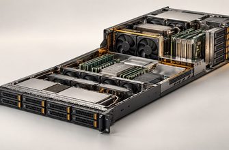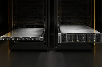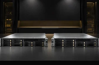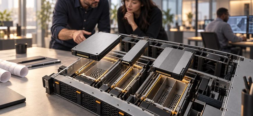
Choosing between U.2, E1.S, and E3.S NVMe SSDs is a server architecture decision, not a cosmetic choice. The form factor determines which chassis you can buy, how many drives fit in each rack unit, how effectively the system cools them, whether they can be replaced from the front, and how easily the platform can accommodate future PCIe generations and higher-power devices.
For conventional enterprise deployments, U.2 remains the lowest-risk option when compatibility, supply breadth, and reuse of existing infrastructure matter most. E1.S is strongest in performance-dense 1U systems. E3.S is the more flexible choice for new enterprise platforms that need efficient cooling, front serviceability, and room for storage or other PCIe devices.
The best form factor is therefore the one supported by the complete server design. A technically superior drive has no value if the backplane, carrier, airflow, firmware, or service model does not support it.
- U.2 vs E1.S vs E3.S at a Glance
- The Form Factor Does Not Define SSD Performance by Itself
- When U.2 Is the Safer Choice
- Where U.2 becomes restrictive
- When E1.S Is the Better 1U Option
- Why E1.S is not an automatic U.2 replacement
- When E3.S Is the Stronger Long-Term Platform
- The flexibility advantage
- Density Must Be Measured at the Chassis Level
- Cooling and Power Can Decide the Purchase
- Serviceability and Spare Strategy
- Do Not Confuse Form Factor With Interface or Protocol
- Common Procurement Mistakes
- Recommendations by Server Scenario
- Procurement Checklist
- Final Recommendation
U.2 vs E1.S vs E3.S at a Glance
| Decision factor | U.2 | E1.S | E3.S |
|---|---|---|---|
| General shape | Traditional 2.5-inch drive | Short, narrow EDSFF device | Wider short EDSFF device |
| Primary strength | Compatibility and mature server support | High drive density in 1U systems | Cooling, power flexibility, and platform versatility |
| Typical deployment | Existing enterprise servers and storage arrays | Dense 1U compute and storage platforms | Modern 1U or 2U enterprise platforms |
| Front serviceability | Common in supported chassis | Designed for front-accessible service | Designed for front-accessible service |
| Thermal design | Mature but constrained by the legacy 2.5-inch envelope | Multiple thickness options allow different heatsinks and power levels | Designed around efficient airflow and higher device power envelopes |
| Device flexibility | Primarily storage | Primarily compact storage | Can accommodate storage and other PCIe device types |
| Migration risk | Lowest for established U.2 fleets | Requires an E1.S-specific chassis and carriers | Requires an E3-compatible server platform |
The Form Factor Does Not Define SSD Performance by Itself
U.2, E1.S, and E3.S describe physical, mechanical, electrical, and connector characteristics. They do not guarantee a specific capacity, NAND type, endurance rating, latency, PCIe generation, or workload performance.
The same SSD family may be sold in several form factors. Solidigm, for example, offers members of its PCIe 5.0 D7-PS1010 family in U.2, E1.S, and E3.S versions. That allows buyers to compare different chassis architectures without assuming that the form factor alone changes the underlying storage class.
When comparing drives, separate two decisions:
- Which server form factor and backplane architecture should the fleet adopt?
- Which SSD model, capacity, endurance class, and firmware qualification should populate it?
Do not use the performance specification of one U.2 product to represent all U.2 drives, or one EDSFF product to represent every E1.S or E3.S drive.
When U.2 Is the Safer Choice
U.2 packages an NVMe SSD in the familiar 2.5-inch enterprise drive shape. Its main advantage is not maximum density or architectural novelty. It is the maturity of the surrounding ecosystem.
Servers, storage arrays, carriers, backplanes, cabling systems, spares, and operating procedures are widely available for 2.5-inch devices. Organizations with an established U.2 fleet may already have qualified drive models, replacement procedures, firmware workflows, and spare inventory.
Choose U.2 when:
- you are adding capacity to an existing U.2 platform;
- you want the broadest choice of conventional enterprise servers;
- your organization already stocks compatible U.2 spares;
- the required capacity and performance fit within available bays;
- you want to minimize platform transition risk;
- the server vendor has not qualified an appropriate EDSFF configuration;
- you expect to reuse existing chassis, carriers, or storage infrastructure.
U.2 is especially defensible for incremental purchases. Replacing a validated U.2 architecture with EDSFF solely because the newer form factor appears more advanced can increase cost without improving the workload.
Where U.2 becomes restrictive
The 2.5-inch envelope was not designed specifically around modern flash density, high-speed PCIe signaling, or the thermal demands of increasingly powerful SSD controllers. It occupies more front-panel area than narrower alternatives and can limit the number of drives available in a 1U chassis.
This matters when performance per rack unit, capacity per rack unit, or airflow through the drive cage becomes a binding constraint. U.2 may also provide less flexibility for platforms intended to mix storage with other front-accessible PCIe devices.
When E1.S Is the Better 1U Option
E1.S belongs to the Enterprise and Data Center Standard Form Factor family. It is a short, narrow device developed for dense server and storage designs. Unlike a bare M.2 module, E1.S is intended to provide enterprise-oriented serviceability, thermal design, and mechanical protection.
E1.S is available in several thicknesses. The selected thickness affects heatsink size, airflow spacing, and the power envelope that a chassis can support. Buyers therefore need to specify more than “E1.S.” A server designed for one E1.S thickness may not accept every other implementation in the same way.
Choose E1.S when:
- high NVMe drive count in a 1U chassis is a primary requirement;
- the workload benefits from high aggregate IOPS or throughput per rack unit;
- front-accessible replacement is required;
- the platform is designed specifically around E1.S airflow and carriers;
- compact flash storage is more important than support for broader PCIe device types;
- you are building a standardized fleet rather than extending a U.2 installation.
Likely use cases include dense compute nodes, performance-focused storage servers, caching systems, content-delivery infrastructure, and specialized AI platforms that need compact local storage near compute devices.
Why E1.S is not an automatic U.2 replacement
Higher bay density is valuable only if the server can support the required PCIe lanes, cooling, power, and software architecture. Installing more drives does not guarantee proportional performance when they share constrained uplinks or PCIe switches.
Additional devices also increase the number of failure points and the amount of telemetry, firmware, and spare inventory the operator must manage. If a server needs only four or six drives, the density advantage of E1.S may have little practical value.
Availability must also be evaluated at the complete-platform level. A drive vendor may offer a suitable E1.S SSD while the preferred server model, reseller, or support contract does not.
When E3.S Is the Stronger Long-Term Platform
E3.S is a wider EDSFF device intended for enterprise servers and storage systems. SNIA describes the E3 family as an update to the traditional U.2 2.5-inch form factor, designed more effectively around flash density, chassis integration, airflow, and future PCIe requirements.
A standard E3.S device is 76 mm high, 112.75 mm long, and 7.5 mm wide. A double-thickness E3.S 2T version uses a 16.8 mm width. The wider physical envelope provides room for thermal solutions and components while remaining more purpose-built for modern servers than the legacy 2.5-inch shape.
Choose E3.S when:
- you are procuring a new server generation rather than maintaining a legacy design;
- the system must support higher-power or higher-performance PCIe devices;
- front-accessible hot-plug service is important;
- cooling efficiency is a major chassis design criterion;
- the platform may mix SSDs with accelerators, networking, or other PCIe device types;
- you want an architecture designed for future PCIe generations;
- the preferred server vendor has a mature E3.S qualification and support roadmap.
E3.S is particularly attractive for modern 2U systems, composable infrastructure, high-performance storage, GPU servers, and platforms where the front bays may need to support more than one class of PCIe device.
The flexibility advantage
SNIA notes that the E3 connector architecture can accommodate x4, x8, or x16 PCIe host interfaces and device power envelopes up to 70 W. That does not mean every E3.S SSD or chassis supplies all those capabilities. It means the broader E3 design can support more varied device classes than a conventional four-lane storage bay.
For buyers, the practical value is platform optionality. An E3-oriented server can potentially support storage today and other qualified PCIe devices later. This is useful when future configurations are uncertain, but only vendor-supported combinations should be treated as deployable options.
Density Must Be Measured at the Chassis Level
Comparing the width of individual drives is not enough. Chassis vendors decide how many bays fit, how much airflow passes through them, where fans and power supplies are placed, and how PCIe lanes reach each connector.
Request a complete system diagram showing:
- the number and type of front bays;
- supported E1.S or E3.S thicknesses;
- PCIe generation and lane width per bay;
- whether bays connect directly to CPUs or through switches;
- oversubscription between drives and the host;
- maximum supported drive power;
- fan configuration and thermal restrictions;
- which bays support hot-plug operation;
- limitations created by GPUs, NICs, or other adapters.
A server with many physical bays can still have less usable aggregate bandwidth than a system with fewer direct-attached drives. Compare usable architecture, not front-panel appearance.
Cooling and Power Can Decide the Purchase
Modern NVMe SSDs can sustain significant power levels, and the thermal problem becomes harder as drive density increases. Cooling affects performance because an SSD may reduce its speed when temperature limits are reached.
E1.S offers different thicknesses partly to accommodate different thermal requirements. A thicker E1.S device can provide more heatsink area but consumes more front-panel space. E3.S provides a larger envelope and airflow-oriented geometry that can suit higher-power devices. U.2 remains practical when a chassis has already been validated around the thermal characteristics of 2.5-inch drives.
Ask the server vendor for supported drive power under the intended inlet temperature and fan configuration. Avoid calculations based only on the SSD manufacturer’s maximum power rating. The chassis must cool all installed devices simultaneously, along with CPUs, memory, network adapters, and accelerators.
Also include fan energy in the operating-cost model. A configuration that requires aggressive fan speeds to cool dense storage can consume more power and create more noise than the drive specifications suggest.
Serviceability and Spare Strategy
All three form factors can support serviceable enterprise deployments, but practical serviceability depends on the server implementation. Confirm that the selected bays, carriers, firmware, and operating system support the required hot-plug workflow.
Consider how technicians identify and replace a failed device. Front-accessible carriers, activity and fault indicators, clear bay numbering, and management-controller integration can matter more during an incident than small benchmark differences.
Introducing a new form factor also creates a spare-parts obligation. A fleet using U.2, E1.S, and E3.S may need separate spare drives, carriers, firmware packages, and handling procedures. Standardization can reduce this burden, but forcing one form factor across unsuitable workloads can create a different kind of inefficiency.
A sensible approach is to standardize within server classes:
- U.2 for legacy-compatible or general-purpose enterprise nodes;
- E1.S for dense 1U storage and compute designs;
- E3.S for new high-power or flexible enterprise platforms.
Do Not Confuse Form Factor With Interface or Protocol
NVMe defines how the host communicates with non-volatile storage. PCIe provides the transport. The form factor defines how the device is packaged and connected physically.
A U.2 drive can use PCIe 4.0 or PCIe 5.0. E1.S and E3.S products can also be offered across different PCIe generations. The presence of an EDSFF connector does not guarantee that every bay operates at the fastest available link rate.
Likewise, physical compatibility does not prove firmware qualification. Server vendors may restrict supported drives by model, capacity, firmware revision, power profile, or carrier type. Verify the exact server bill of materials before purchasing.
Common Procurement Mistakes
- Choosing the drive before choosing the chassis. The server architecture determines which form factors, thicknesses, power levels, and interfaces are usable.
- Treating all E1.S devices as physically identical. Multiple thickness options exist, and chassis support must be verified.
- Assuming more bays mean more performance. Shared PCIe switches or constrained host links can limit aggregate throughput.
- Replacing U.2 without a business requirement. A form-factor migration should solve a density, cooling, serviceability, or roadmap problem.
- Ignoring the spare inventory. Adding another physical standard increases operational complexity.
- Equating EDSFF with PCIe 5.0. Form factor and interface generation are separate purchasing criteria.
- Buying unqualified drives. Mechanical fit does not guarantee firmware, thermal, hot-plug, or support compatibility.
- Using maximum drive power as the only thermal input. Cooling must be validated for the populated server under realistic environmental conditions.
Recommendations by Server Scenario
| Server scenario | Recommended starting point | Why |
|---|---|---|
| Expanding an existing U.2 fleet | U.2 | Preserves compatibility, spares, and operational procedures |
| General-purpose enterprise server | U.2 or vendor-standard E3.S | Choose the platform with the strongest qualification and supply chain |
| High-density 1U storage | E1.S | Compact dimensions can increase performance and capacity per rack unit |
| 1U compute node with several local SSDs | E1.S | Efficient front-accessible storage in a space-constrained design |
| New 2U high-performance platform | E3.S | Strong cooling, serviceability, and device flexibility |
| Mixed storage and PCIe device architecture | E3.S | The broader E3 design can support more device types and lane configurations |
| Lowest-risk incremental purchase | U.2 | Mature ecosystem and broad established support |
| Long-lived platform with changing I/O needs | E3.S | Provides more architectural flexibility when the server vendor supports it |
Procurement Checklist
- Which form factors and thicknesses does the exact server model support?
- How many usable bays are available after the complete configuration is installed?
- What PCIe generation and lane width reach each bay?
- Are any drive connections oversubscribed?
- What is the validated power limit per drive and for the complete drive cage?
- Can the chassis cool a fully populated configuration at the required inlet temperature?
- Does the system support front replacement and hot-plug operation?
- Which SSD models and firmware versions are qualified by the server vendor?
- Are suitable capacities and endurance classes available in the selected form factor?
- Can replacement drives and carriers be sourced throughout the server’s service life?
- Will adopting the form factor reduce or increase spare inventory?
- Does the migration solve a measurable density, cooling, performance, or serviceability problem?
Final Recommendation
Choose U.2 when compatibility, purchasing flexibility, and reuse of established enterprise infrastructure matter more than maximum density. It remains the disciplined choice for expanding existing fleets and for servers whose storage requirements fit comfortably within conventional 2.5-inch bays.
Choose E1.S for purpose-built 1U systems where storage density, aggregate IOPS, and front serviceability are central requirements. Verify the precise drive thickness, cooling design, power envelope, and PCIe topology before committing.
Choose E3.S for new enterprise platforms that need an airflow-oriented design, higher device flexibility, and a stronger path toward future storage or other PCIe devices. It is particularly well suited to modern 2U and high-performance systems, provided the server vendor has a mature qualification and support roadmap.
Do not migrate form factors simply to adopt the newest standard. Make the change when it produces a concrete improvement in density, cooling, serviceability, performance per rack unit, or platform flexibility. If those benefits cannot be quantified, the most mature supported option is usually the better purchase.